



Bolt Anchor Lifting Socket for Shallow Precast Elements
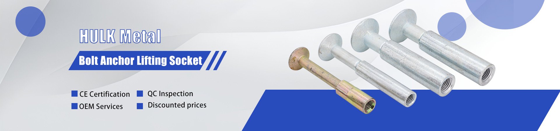
Thin wall panels, shallow beams, slabs and compact architectural units can leave too little room for a conventional long-tail lifting insert. A bolt anchor lifting socket addresses this constraint with a more compact anchorage. It should not, however, be treated as a simplified lifting solution.
A shallow socket concentrates force within a smaller volume of concrete. The steel component may remain intact while the surrounding material cracks or splits if thickness, edge distance, reinforcement or load direction is unsuitable. Selection must therefore confirm the complete socket-and-concrete system, not merely the shortest product that fits the drawing.
This guide evaluates four essentials: available geometry, real lifting action, concrete and reinforcement conditions, and compatibility with the lifting accessory. Material choice and quality evidence complete the review.
What Is a Bolt Anchor Lifting Socket?
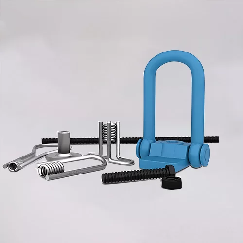
A bolt anchor lifting socket combines a threaded sleeve with an anchor bolt or rod. The sleeve provides the internal lifting thread at the concrete surface. The bolt head or verified end anchorage transfers force into the surrounding concrete.
The unit is positioned before casting, with its thread aligned to the lifting face and its anchorage fully embedded. Once the required concrete strength is reached, a compatible lifting loop or other approved accessory can be connected.
The concept suits shallow embedded elements that do not require a long reinforcement tail. Standard mesh and specified edge reinforcement are still essential, and angled lifting generally needs additional reinforcement. Confirmation must come from the approved drawing and model-specific technical data.
This product is not interchangeable with a fixing socket that happens to use the same thread. Lifting and fixing products may follow different design assumptions and must not be substituted without technical approval.
Why Shallow Precast Needs a Separate Check
A deep concrete section can distribute local anchor pressure over a substantial volume. In a shallow element, the socket may sit close to the opposite face, a free edge, an opening or congested reinforcement. The bolt head can then impose high local pressure on a limited concrete area.
Catalogue dimensions define product limits; they do not replace a check of spacing, concrete cover, edge distance, construction joints and reinforcement continuity. Movement during casting can also reduce the available cover or damage the connection, while concrete ingress may prevent full accessory engagement.
Follow the Complete Load Path
Lifting force travels from the crane and accessory into the internal thread, sleeve, anchor rod and end anchorage before entering the reinforced concrete. The usable capacity belongs to the weakest verified part of this path.
Failure may involve the accessory, thread, socket body, anchor pull-through, concrete splitting or another local mechanism. A successful steel test therefore does not establish the capacity of a thin concrete member. Conversely, a concrete assessment cannot compensate for a damaged or incompatible thread.
Published data may distinguish lifting from fixing, axial from angled loading, and different concrete or edge conditions. Those qualifiers must remain attached to each value. Never transfer a capacity from one product model or load case to another by assumption.
Step 1: Confirm the Available Anchorage Geometry
Begin with the precast drawing. Check element thickness, edge distances, concrete cover, reinforcement, voids and nearby embedded items. Review the socket, bolt-head anchorage and required reinforcement as one assembly rather than checking the sleeve alone.
The approved position must leave enough concrete and confinement around the anchor. Two sockets acting together may also require sufficient centre spacing to prevent interacting stress zones. Keep the opening aligned and square to the lifting face as specified.
During casting, the socket must be secured against movement, and the thread should be protected without relying on a cap to correct position. After stripping, confirm that concrete has not entered the socket and that the anchorage area shows no cracking, spalling or voiding.
If the drawing cannot accommodate the required thickness, edge distance or reinforcement, revise the lift-point design or use another approved lifting system. Choosing a larger socket may increase anchorage demand rather than solve the constraint.
Step 2: Define the Actual Lift
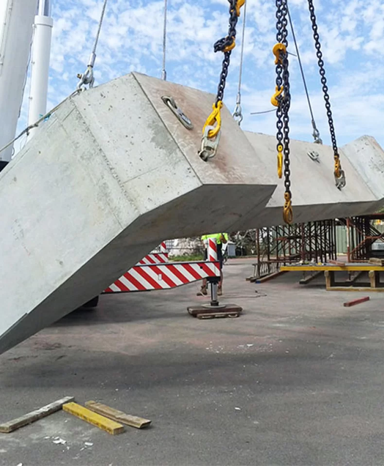
Element weight is only the first input. The lifting plan must also consider the centre of gravity, active lifting points, sling angles, mould adhesion, acceleration, braking, transport and final erection. Unequal sling lengths or eccentricity can make one socket carry much more than its nominal share.
Each unit should be checked for the tension, shear or combined action assigned by the plan. Published guidance for bolt anchor lifting sockets generally limits normal lifting to a specified angle and requires additional reinforcement for angled operations. Turning or pitching requires separate reinforcement and technical approval; it should not be assumed to fall within ordinary lifting limits.
Where the operation exceeds the applicable geometry, angle or load condition, change the lifting method or obtain an engineering review. A larger socket is not a substitute for correcting the direction of load or strengthening the concrete.
Step 3: Verify Concrete and Reinforcement
Handling must begin only after the concrete has reached its specified strength. Visible surface hardness is not an acceptable substitute for a recorded test. This matters especially in shallow sections, where internal damage around the anchor may not initially be visible.
Standard mesh reinforcement, edge bars and any diagonal or confining steel specified for the lift are essential. These bars resist the local splitting and bursting action created by the bolt-head anchorage. Their size, position, continuity and cover must follow the drawing.
A generic cage is not automatically adequate for every load direction. Reinforcement should be arranged to resist the calculated force and should not be displaced during concreting. Missing edge steel can alter the failure mode even when the socket has been installed at the correct depth.
Load data may be based on stated concrete strength and reinforcement assumptions. Match the selected capacity to the actual verified condition, and do not combine values taken from different lines of a table.
Step 4: Match the Thread and Accessory
Confirm thread form, diameter, pitch and engagement. M and Rd threads are not interchangeable. The lifting accessory must also have a suitable rated capacity and be permitted for the planned load direction.
The accessory should seat correctly and maintain full engagement. A contaminated or damaged thread must be assessed before use; forcing the connection or accepting partial engagement is not acceptable. Some lifting loops are intended mainly for near-vertical work and are unsuitable for turning. Socket and accessory should therefore be recorded as a matched assembly in the lifting plan.
Step 5: Select Material and Protection
Carbon steel sockets usually require a protective coating, while stainless steel may be selected for exposed architectural or corrosion-sensitive applications. Electro-galvanized and hot-dip galvanized finishes can serve different storage and exposure requirements.
Material selection cannot compensate for inadequate cover, missing reinforcement or thread damage. Confirm that the finish suits the service environment and that threads remain functional. Batch identification helps connect the delivered product with its material, coating and inspection records.
Installation and Pre-Lift Verification
Before casting, verify the model and position, secure the socket, install the specified reinforcement and protect the internal thread. Prevent displacement and damage during concrete placement and stripping.
Before lifting, check the concrete strength, socket identification, thread condition, accessory compatibility and actual rigging angle. Confirm full engagement and that the reinforcement surrounding the socket remains as approved. Stop the operation if cracking, movement, deformation or any other abnormal condition appears.
Common Mistakes
Do not select by tonnage alone, treat every short socket as suitable for shallow concrete, substitute a fixing socket, mix M and Rd threads, omit edge reinforcement or ignore turning and angled loading. These errors may remain hidden because the socket can physically fit and accept an accessory. The selection record should demonstrate why the complete system is suitable, not merely that it is available.
A bolt anchor lifting socket can be effective for shallow precast elements because it avoids dependence on a conventional long reinforcement tail. Its performance still depends on element geometry, actual lifting action, concrete strength, reinforcement and accessory compatibility.
For a reliable selection, send the drawing, thickness, weight, edge distances, lifting angle, thread, concrete strength, reinforcement details and finish requirements to HULK Metal for a model-specific technical review.
Article Navigation
PRECAST CONCRETE ACCESSORIES
OTHER RELATED ARTICLE
- 1.How to use Wavy Tail Anchor to improve construction efficiency and safety
- 2.How to Choose High-Quality Shuttering Magnetic Products and Suppliers Guide
- 3.Applications and advantages of swivel hoist rings: HULK Metal provides you with safer and more flexible lifting solutions
- 4.Lifting Clutch VS Lifting Ring Clutch:Definition, Working Principle, Application Scenarios, and Selection Guide
- 5.Lifting Socket: Types and Selection Guide
Other Precast Concrete Accessories You Might Want to Know
You can click to learn more about HULK Metal precast concrete accessories such as lifting anchors, precast sockets, spread anchors, shuttering magnets, cast-in channels, wire loop boxes, and other precast concrete accessories you might want to know.