



Utility Lift System for Precast Concrete: Applications, Selection, Installation, and Safety
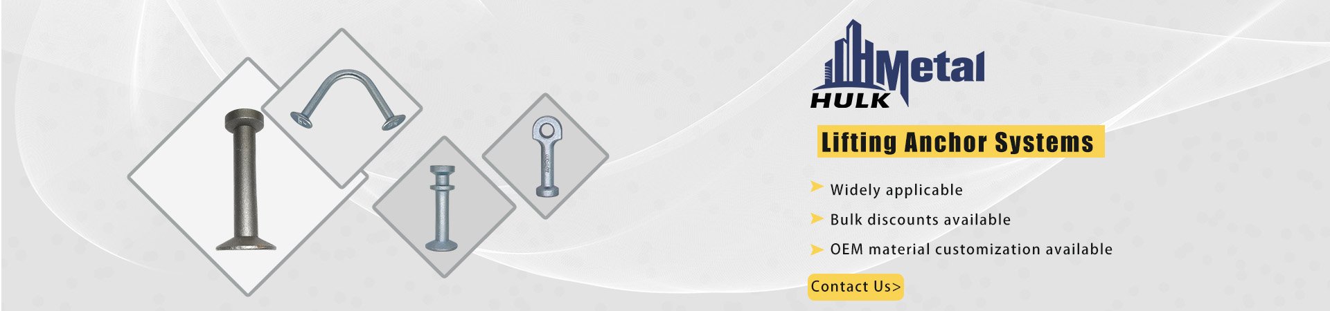
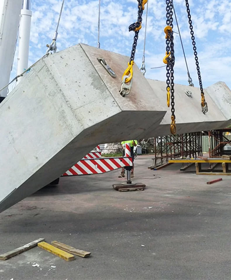
Precast concrete units require controlled lifting during stripping, storage, transport, and installation. A Utility Lift System creates planned cast-in lifting points for underground utility structures, sanitation and grease interceptor units, pump stations, and manholes of different sizes. These products often restrict slinging access, so an engineered lifting arrangement is more practical than a general-purpose solution.
This article explains how the system works, where it is used, and what must be checked before selection and installation. The key principle is that the anchor, recess former, lifting accessory, concrete section, and approved lift plan must work together. A load rating alone does not make a system suitable for an element.
What Is a Utility Lift System?
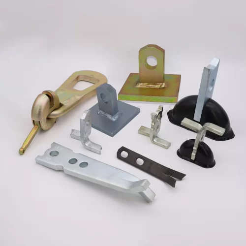
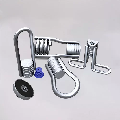
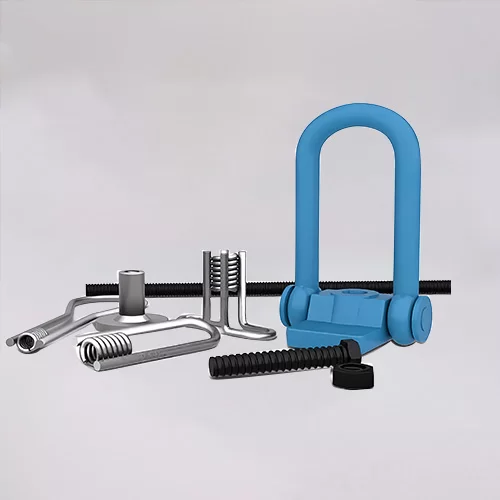
A Utility Lift System is a cast-in arrangement for precast concrete. It normally combines a utility lifting anchor, a recess former that creates an accessible pocket, and a compatible hook, eye hook, clevis, or shackle. The anchor is fixed in the formwork before casting. Once the concrete reaches the required lifting strength, the recess former is removed and the lifting accessory is connected through the exposed pocket.
This arrangement combines an engineered load path with practical access. The lifting point does not remain exposed throughout production, and the finished component does not require an open through-hole solely for handling. The load passes from the lifting accessory through the anchor into the surrounding concrete.
Utility anchors should not be confused with every other precast lifting insert. Spherical-head, double-head, lifting-eye, and utility anchors can differ in head geometry, clutch interface, recess design, and permitted concrete conditions. Product names are sometimes used loosely, so selection should begin with the element and lifting operation rather than an assumed equivalent.
Key Features and Benefits
A Utility Lift System can create a reliable lifting point without complex, product-specific lifting machinery. Depending on the design, a suitable eye hook or shackle may engage the anchor directly. The connection must still match the anchor geometry and rated capacity; convenience should not be mistaken for interchangeability.
The system suits repeat production because anchors can be positioned consistently in the mould and recess formers can be reused. Many designs use 45-degree or 90-degree polyurethane recess plugs to produce a clean, repeatable pocket. Other benefits include straightforward installation, hook-based lifting, and elimination of unnecessary through-holes.
These benefits depend on proper use. A utility anchor is not universally safe for every direction, concrete grade, or section thickness. Accepted load, installation position, concrete strength, and lifting accessory must be confirmed against the product data and lift plan.
Typical Applications
Typical applications include precast vaults, chambers, pump station components, sanitation structures, grease interceptors, and manhole sections. Walls, slabs, and access openings often restrict lifting-point placement, making a planned cast-in system preferable to improvised slinging.
The system may also suit precast boxes, pipes, barriers, slabs, and other reviewed units. Handling duties can include stripping, turning, yard movement, loading, unloading, transport, and installation.
Each stage can create a different load condition. A vertical lift from the casting bed is not the same as tilting a panel, lifting a box at four points, or moving an asymmetrical manhole section. Selection should cover the most demanding approved stage.
Installation Position and Structural Limitations
Anchor placement is a critical design decision. Utility anchors are generally intended for suitable vertical or horizontal concrete surfaces. They should not be installed along a thin base-slab edge, the narrow top edge of a box wall, or another area with little concrete around the anchor.
Thin-edge installation reduces the concrete volume available to resist concentrated lifting force. It can also conflict with cover, reinforcement, and recess access. Moving the lifting point or selecting another anchor family may be safer than forcing a utility anchor into an unsuitable location.
The final position should be checked against reinforcement, edge distance, point spacing, section thickness, and load direction. A larger anchor does not automatically solve an edge-distance problem and may reduce cover or create interference.
How to Select the Correct Utility Lift System
Selection starts with the lifting plan: element type, dimensions, weight, and number of lifting points. Dividing total weight by the number of points is only an initial check. Uneven load distribution and dynamic effects during stripping, turning, crane movement, or transport can make one point carry more than its static share.
The concrete strength at the time of lifting must be confirmed separately from the final design strength. An anchor’s permitted load is tied to stated concrete conditions, so a final-design value cannot be used before the concrete has reached that strength.
Section thickness, cover, edge distance, and reinforcement are equally important. The anchor needs enough sound concrete to transfer the load, while the recess former must fit without interfering with reinforcement and leave clear access for the hook or shackle.
The lift angle and movement sequence also affect the load path. Vertical lifting, angled pulling, tilting, and rotation should not be treated as equivalent. Hook contact with the concrete can introduce prying action, so any change in direction must be included in the approved plan.
The anchor, recess former, and lifting accessory should finally be confirmed as a matched set. Similar-looking products should not be mixed without written confirmation. Even comparable nominal capacities may use different head geometry, clutch interfaces, pocket depths, or concrete conditions.
Step-by-Step Installation and Lifting Procedure
Installation begins with an approved drawing. Mark the lifting-point coordinates, orientation, recess access, and pull direction before preparing the mould, then check the anchor and former against cover and reinforcement.
Fix the anchor so it cannot move during concrete placement. The former should close correctly around the head and remain tight against the formwork. A loose former can allow cement paste into the pocket, while vibration can displace the lifting point.
Compact the concrete carefully around the anchor. Poor consolidation can leave voids in the region responsible for transferring the lifting load. Inspect the anchor after vibration to confirm that it has not moved.
Before stripping, confirm that the concrete has reached the required lifting strength and that the lift angle matches the approved condition. Remove the former, clean the pocket, and inspect the anchor head for damage, deformation, or obstruction.
Check the lifting accessory for the correct type and size before connection. Follow the approved sequence without sudden loading, hook contact with the concrete, or movement beyond the permitted angle. After use, clean, inspect, and store the former and reusable equipment so damage is not carried into the next cycle.
Common Installation and Selection Mistakes
A common error is selecting an anchor only from total element weight. This ignores effective lifting points, load distribution, and the most demanding handling condition. Another is relying on final 28-day strength when the unit will be stripped earlier.
Mixed lifting sets are also risky. An anchor, former, hook, or clutch should not be substituted merely because it looks similar or has a comparable tonnage marking. Compatibility must be confirmed by model and load group.
Incorrect edge placement, insufficient embedment, displaced formers, inadequate compaction, and reinforcement interference can reduce performance. Damaged hooks and lifting components repaired by welding, heating, or bending should not be used.
Inspection, Quality Control, and Compliance
Quality control begins before the anchor reaches the casting bed. Material grade, dimensions, head geometry, body dimensions, finish, and batch identity should be checked against the order. Traceability matters because the visible anchor is only one part of a system that also depends on the recess, accessory, and surrounding concrete.
Certificates and test documents should be linked to the exact product and order. A CE marking, ISO 9001 certificate, inspection record, or test report should not be applied automatically to another product family or an unverified batch. Projects may also require specific tensile tests, dimensional records, witness points, or third-party inspection.
Reusable lifting equipment requires its own inspection routine. It should be examined before use and periodically by a competent person. Deformation, excessive wear, cracks, missing identification, or damage to the lifting interface should lead to withdrawal from service. Geometry-altering repairs should not be accepted unless expressly authorized.
Why Choose HULK Metal?
HULK Metal offers utility lift anchors in several published load groups, including 0.8 t, 1.4 t, 2.0 t, and 2.5 t options. This provides an application-based starting point rather than a single standard size. The selection can be reviewed against the element drawing, concrete strength at stripping, lift angle, section thickness, and the lifting equipment already used in the yard.
HULK Metal’s lifting-anchor catalogue is covered by an ISO 9001 quality system and lists CE for the lifting-anchor family. The applicable certificate, batch identification, inspection record, and test scope should be confirmed for the exact product and order. Controls include checks on incoming material, dimensions, head geometry, rod diameter, and batch identity. Raw, electro-galvanized, and hot-dip galvanized finishes can also be specified according to the product and project requirements.
For projects outside a standard catalogue combination, HULK Metal can review made-to-drawing lengths and project-specific documentation. Its approach recognizes that the specification is complete only when the anchor, accessory, concrete section, installation position, and lift plan are considered together. This combination of product range, traceable quality controls, customization, and application-based review makes HULK Metal a practical partner for projects where safety and dimensional fit must be verified before delivery.
Article Navigation
PRECAST CONCRETE ACCESSORIES
OTHER RELATED ARTICLE
Other Precast Concrete Accessories You Might Want to Know
You can click to learn more about HULK Metal precast concrete accessories such as lifting anchors, precast sockets, spread anchors, shuttering magnets, cast-in channels, wire loop boxes, and other precast concrete accessories you might want to know.