



Lifting Loops in Modern Construction: Design, Use and Quality Control
A Small Component in a Critical Load Path
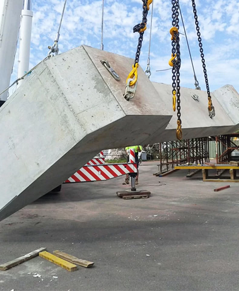
Modern precast construction depends on repeated handling. Wall panels, beams, columns, slabs, piles, pipes and tunnel segments are stripped from moulds, moved around production yards, stacked, loaded for transport and finally erected on site. Each operation transfers the weight of a substantial concrete element through a small number of lifting points.
Lifting loops provide one of the most efficient ways to create those points. However, their performance cannot be established from a nominal working load alone. The loop operates as part of a system that includes its wire rope and termination, the threaded end or embedded anchorage, the concrete surrounding it, the crane hook, the rigging and the planned lifting geometry.
A professional specification therefore links product selection to the element drawing, installation conditions, inspection records and service life. This article examines those controls across design, production, handling and procurement.
What a Lifting Loop Does in Precast Construction
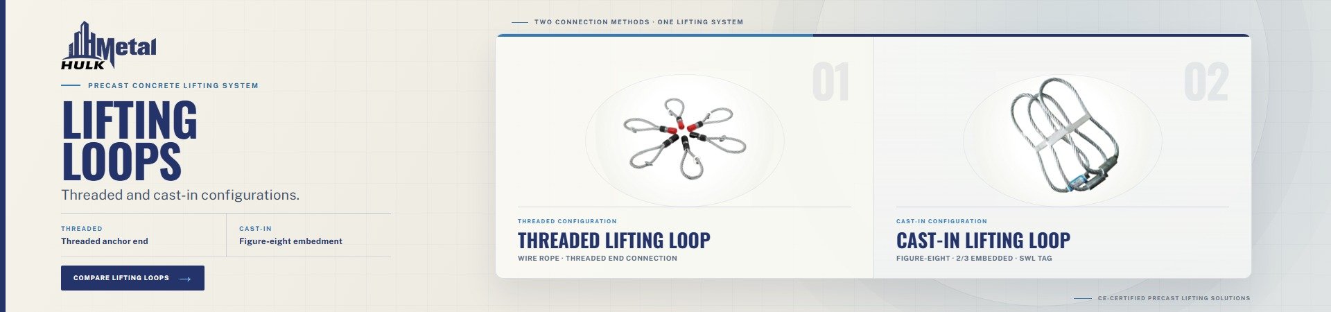
A lifting loop is a wire rope assembly that forms a crane attachment point on a concrete element. There are two principal configurations in precast work.
A threaded lifting loop has a rigid threaded end connected to a galvanized steel wire rope. The thread engages a cast-in socket, allowing the loop to be fitted after the concrete has reached the required strength and removed after handling.
A cast-in lifting loop is installed in the formwork before concrete placement. Its anchorage and part of the rope become embedded, while the lifting eye projects above the surface. This type is generally intended for a single handling cycle from production to final installation and requires careful control of embedment, projection, edge distance and orientation.
In both configurations, force passes from the crane hook through the rope loop and termination into the embedded component and surrounding concrete. The lifting plan must therefore determine the number, position and required capacity of the lifting points rather than relying only on the total mass of the unit.
Design and Material Selection
Selection begins with the actual load carried by each lifting point. Weight, centre of gravity and handling sequence determine the load distribution, while acceleration, braking and other crane movements may create effects beyond a static calculation. These factors belong in the project-specific lifting plan and structural design.
The published safe working load is an upper operating limit under the defined conditions of the lifting system. It does not authorise an unplanned direction of pull. A loop selected for a near-vertical lift may not be suitable for turning, pitching or a substantial side load, even if its nominal capacity appears adequate.
Connection compatibility is equally important. For a threaded loop, the thread form, nominal size and engagement must match the cast-in socket. M and Rd threads are different forms and should not be treated as interchangeable. The thread must seat as required by the manufacturer's procedure and must not be forced into a damaged or contaminated socket.
For a cast-in loop, the design must establish embedment depth, projection, edge distance and reinforcement requirements. Positioning affects both hook access and force transfer, so deviations from the approved drawing should be reviewed before casting rather than corrected after the concrete has hardened.
Material and finish should reflect the service environment. Galvanized steel wire rope is commonly used to resist corrosion during storage and transport and reduce rust staining on exposed concrete. Stainless steel or other project-specific options may suit aggressive conditions, but finish cannot compensate for an incompatible socket, inadequate concrete strength, a damaged anchorage or an unsuitable lifting angle.
Applications and Operational Benefits
Lifting loops are used across a broad range of precast products. Wall panels, beams, columns and slabs require point layouts that control orientation and surface damage, while pipes, piles, manholes and tunnel segments require lifting points that remain accessible in the intended handling attitude.
The operational value of a properly selected system is based on consistency. Repeated elements can be lifted with a defined hook position, compatible rigging and a familiar inspection routine. This supports efficient demoulding, stacking and loading, while reducing the risk of improvised attachment methods.
Lifting loops provide a relatively compact connection that can remain close to the concrete surface. Threaded loops can be removed after use, whereas cast-in loops are normally cut after erection and require suitable treatment of exposed ends to control corrosion. These benefits apply only within the intended handling method; HULK's published guidance states that lifting loops are not suitable for turning or pitching.
Installation and Safe-Use Controls
Installation should follow the approved drawing and manufacturer's instructions. Before fitting a threaded loop, confirm its model, working load, thread designation and batch identity, then inspect the socket for concrete residue, contamination, deformation or displacement.
Published HULK guidance requires the concrete to reach 15 N/mm² before a threaded lifting loop is fitted. This is a manufacturer minimum, not an automatic release criterion for every project. The structural specification may require a higher strength according to the concrete mix, element type, lifting load and site conditions. The governing value should be verified and recorded before the first lift.
The thread must be fully bottomed before lifting. HULK permits backing off by no more than one turn when necessary to align the rope with the intended lifting direction. This is not a method for resolving a large rigging offset; if alignment cannot be achieved within that allowance, the lifting arrangement should be reviewed.
The hook and rigging must reproduce the planned load path. Vertical lifting is preferred, and the angle should not normally exceed 30°. A configuration above 45° requires technical consultation with the manufacturer. The range between 30° and 45° should also follow the specific procedure and approval applicable to the project rather than being treated as an unrestricted operating zone.
Contact between the wire rope and sharp edges, damaged recesses or incompatible hardware should be avoided. Tension should be applied in a controlled manner, with the loop, socket and concrete observed before the element is raised clear of its support. Any abnormal movement, noise, deformation or cracking should stop the operation.
Inspection, Reuse and Traceability
Lifting loops should be inspected before every use. Check the wire rope for bends, crushing, kinks, corrosion and loosening of the outer layer, and examine the threaded end, ferrule, markings and general geometry. A damaged loop should be removed from service and not straightened, welded or otherwise repaired without manufacturer authorisation.
Threaded lifting loops may be reused under controlled conditions, but HULK does not recommend them for severe reuse applications. Its published procedure requires retained loops to be inspected every six months and retested every year. These periodic controls are additional to the pre-use inspection.
Traceability connects the physical loop to its inspection history. Each HULK loop is proof loaded before dispatch and marked with a unique batch number. That number should remain linked to the product code, working load, thread designation, proof-load record, inspection dates and any rejection decision.
Cast-in lifting loops generally follow a different model. Because they form part of the finished element and are normally used for one cycle, reuse should not be assumed. Their inspection and positioning must be completed before concreting and again before demoulding, with particular attention to rope damage, contamination and movement within the formwork.
Procurement and Quality Assurance
An accurate quotation requires the element drawing, unit weight, lifting-point layout, required working load, thread type and size, lifting angle, handling sequence, material, finish and applicable project standard. These details allow the supplier and project engineer to assess the loop as a compatible system and determine whether a drawing-based solution is required.
Quality evidence should match the critical nature of the component. Depending on the order, buyers may request material records, dimensional inspection, proof-load documentation, batch marking, surface and thread inspection, and applicable certification. Packing and quantity records should also allow received products to be linked to the approved delivery.
Purchase decisions should therefore not separate price from compatibility and documentation. A low-cost loop that requires additional inspection, cannot be traced or does not match the socket creates avoidable project risk.
Lifting-loop safety is determined by the complete system rather than a single load figure. Correct selection establishes compatibility with the element, connection and lifting geometry. Controlled installation confirms concrete strength, thread engagement and hook position, while inspection and traceability ensure that only serviceable products remain in use.
Vertical lifting should remain the preferred method, 30° should be treated as the normal operating limit, technical consultation is required above 45°, and turning or pitching should remain outside the loop's approved use. These controls should be applied together with the project design, local regulations and manufacturer's instructions.
For a technical review, provide HULK Metal with the element drawing, unit weight, lifting-point layout, socket thread, planned lifting angle and required working load.
Article Navigation
PRECAST CONCRETE ACCESSORIES
Other Precast Concrete Accessories You Might Want to Know
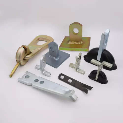
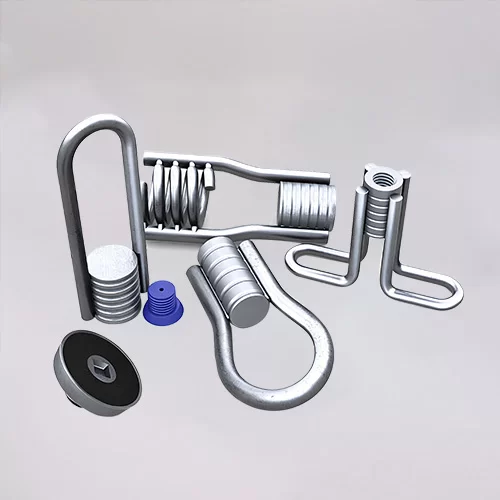
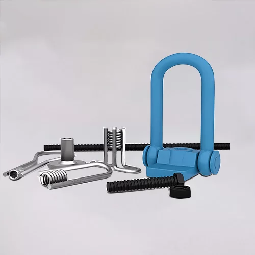
You can click to learn more about HULK Metal precast concrete accessories such as lifting anchors, precast sockets, spread anchors, shuttering magnets, cast-in channels, wire loop boxes, and other precast concrete accessories you might want to know.