



Can a Lifting Clutch Be Used with a Different Anchor System?
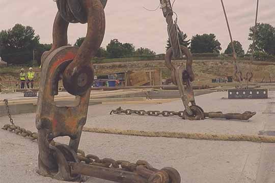
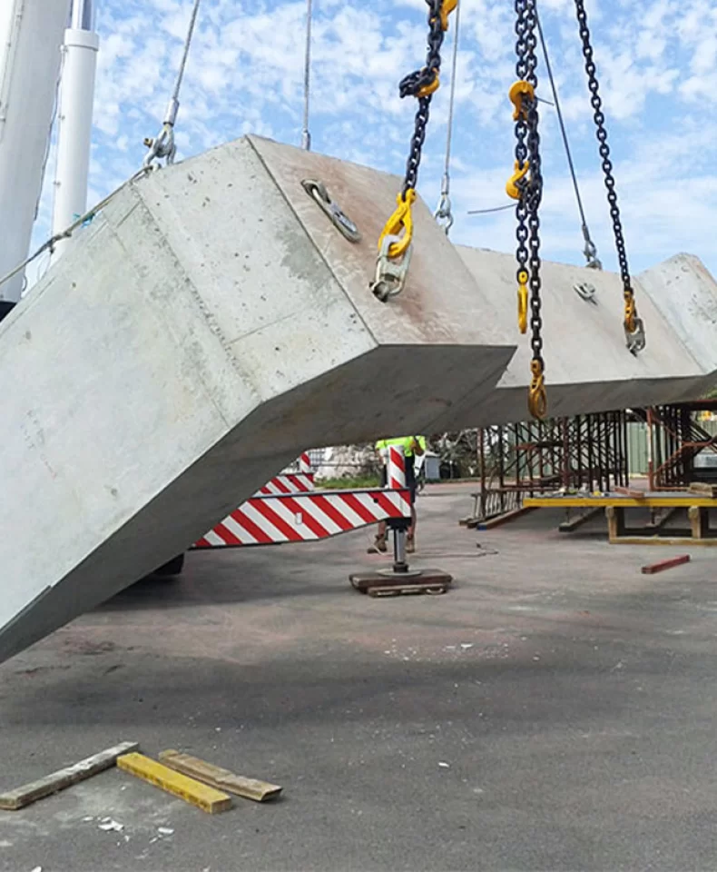
A lifting clutch is the mechanical link between a precast concrete lifting anchor and the crane or hoist used to position the element. In a properly designed system, the clutch is matched to the anchor, the recess former, the reinforcement details, and the approved handling sequence. When these components are considered individually rather than as a system, the connection that looks correct on site may not have the technical basis required to support the lift.
Buyers and lifting coordinators sometimes consider mixing a clutch with an anchor from another manufacturer, product family, or revision. The motivation is understandable: stock availability, lead time, cost, or a mismatch between what was embedded in the element and what is currently held in the lifting equipment inventory. Even with a justified reason, the combination must be treated as unverified until the manufacturer documentation and the project engineer confirm the specific pairing.
The central principle is straightforward. A lifting clutch should not be used with a different anchor system unless the exact combination is supported by current technical documentation and has been approved for the intended lifting application. A clutch that closes around an anchor head has only demonstrated that it can be attached. It has not demonstrated that it can transfer the rated load under the approved handling conditions for the precast element on site.
What Does a Different Anchor System Mean?
A "different anchor system" covers more situations than a simple cross-manufacturer mix. Buyers reviewing compatibility should consider all of the following.
Different Manufacturers
A clutch from one supplier paired with an anchor from another is the most obvious case. Similar descriptions, similar catalogue dimensions, or the appearance of interchangeability do not establish that the two products share a controlled interface. Each manufacturer designs its own head profile, locking geometry, and recess former, and the documentation typically applies only to its own product family.
Different Product Families
Even within one manufacturer, different product families are not automatically interchangeable. A spherical-head anchor, a spread anchor use different head profiles and load transfer principles, and the clutches that fit one family are not approved for another.
Older and Newer Product Versions
Design revisions may change critical dimensions, locking features, or material specifications while keeping the part number similar. An anchor installed several years ago may not match the clutch currently listed in the catalogue, even when both carry the same reference. Current instructions and drawing revisions should always be checked.
Unidentified or Aftermarket Components
Missing or partially legible markings, incomplete traceability, and custom-made replacements create additional uncertainty. Such components should remain out of service until their identity, original manufacturer, and technical status can be confirmed.
Why Physical Fit Does Not Guarantee Compatibility
A trial engagement is useful, but it only answers a narrow question: can the clutch be placed on the anchor? It does not establish load class, locking security, permitted force directions, or performance as part of the proposed lifting system.
Differences in Anchor Head Geometry
Head diameter, neck length, bearing surfaces, and the contour that controls the contact area all affect how load is transferred. A small change in head profile can change the bearing stress, the engagement travel, or the way the clutch lock seats.
Locking Mechanism and Engagement Depth
Clutch openings, locking components, and seating depth determine whether the lock can fully close under load. Differences in recess former geometry, debris in the recess, or coating on the anchor can all change the contact between clutch and anchor and prevent a positive lock.
Load Capacity and Force Direction
Two products with similar Working Load Limit (WLL) markings can still rely on different design assumptions, geometry, and documentation. Capacity markings help identify a component within its intended system; they are not a universal interchange code. Permitted loading directions, sling arrangements, and load distribution must be supported by manufacturer instructions and project calculations.
Manufacturing Tolerances and Wear
Tolerances, surface coatings, contamination, and service wear all influence the connection. A successful hand fit on one sample does not guarantee the same result across a production batch or after a period of use on site.
What Should Buyers Verify Before Using a Different Anchor System?
A controlled compatibility review reduces both the technical and the commercial risk of mixing components.
Confirm the Identity of Both Components
Record the manufacturer, product family, part number, marked load class, drawing revision, and inspection history for the clutch. Record the anchor and recess former with the same level of detail. If either component cannot be positively identified, it should be quarantined until its status is established.
Review Technical Drawings and Instructions
Obtain the current documentation for both products. Confirm whether the documents name the mating component, define engagement requirements, specify permitted loading directions, and state any exclusions. A saved catalogue page may refer to discontinued geometry; record the source, date, and revision rather than relying on an unlabelled image.
Compare Critical Interface Dimensions
Compare the head profile, contact surfaces, clutch opening, locking travel, seating depth, and recess clearance using controlled drawings. The connection is three-dimensional and includes movement under the approved handling sequence, so the comparison should not be reduced to a single diameter.
Request Written Compatibility Confirmation
Ask the relevant supplier to state in writing the exact references covered, the basis of any compatibility claim, the limitations, and the required supporting documents. A general statement such as "compatible with common systems" is not sufficient for approval or purchase.
Obtain Project-Specific Engineering Approval
The responsible engineer should review the complete lifting arrangement, including the precast element, its mass and centre of gravity where established, the concrete condition, anchor positions, reinforcement, sling arrangement, loading directions, and the full handling sequence. A combination approved for one vertical lift should not silently migrate to tilting, rotation, or impact-prone handling.
Conduct Controlled Sample Verification When Required
Traceable samples can support dimensional inspection, engagement observation, and agreed testing. The purpose, method, acceptance criteria, quantity, and witnesses must be defined in advance. A shop-floor pull, an unloaded hand fit, or a video is not a substitute for the required technical evidence.
Compatibility Comparison Table
Verification Item What Buyers Should Check Why It Matters
Product identity Manufacturer, model, and system reference Establishes component traceability
Load class Markings and approved technical ratings Confirms the intended capacity basis
Interface geometry Head profile, contact areas, and tolerances Supports correct mechanical engagement
Locking mechanism Seating and locking operation Helps verify the intended connection
Recess former Profile, depth, and available clearance Supports proper clutch access and movement
Technical documentation Drawings, instructions, and compatibility evidence Defines permitted component combinations
Lifting application Load conditions and handling sequence Determines suitability for the actual operation
Inspection and approval Inspection records and responsible technical approval Supports controlled use and ongoing safety
Risks of Using an Unverified Lifting Clutch and Anchor Combination
Increased Lifting Safety Risks
Incorrect engagement or unsuitable load transfer can compromise the lifting connection and create a direct safety hazard on site.
Damage to Equipment or Precast Elements
Poor seating or unintended contact can damage the clutch, the anchor, or the surrounding concrete, leading to rework or rejected elements.
Project Delays and Additional Costs
Unapproved equipment can be rejected at the point of use, interrupting lifting operations, requiring replacement purchases, and triggering additional inspection work.
Traceability and Compliance Problems
Missing technical evidence makes it difficult to demonstrate that the equipment meets project specifications, applicable standards, or client requirements.
How to Manage Different Anchor Systems in Precast Production
Maintain a documented list of approved anchor and clutch combinations for each product or project.
Separate lifting equipment physically by system, model, and load class rather than relying on colour alone.
Use clear, durable markings and labelled storage so that the crane crew always sees the system and class before use.
Inspect lifting clutches according to the current instructions for the exact reference in use. Wear or damage can invalidate the fit that was originally reviewed.
Quarantine any unidentified, damaged, or unapproved equipment.
Apply change control whenever a supplier, product reference, drawing revision, or manufacturing location changes.
How to Select a Reliable Lifting Clutch Supplier
Product-Specific Compatibility Support
The supplier should be able to identify the intended anchor system and clearly state any limitations on alternative combinations. A reliable supplier will request the existing anchor reference and provide a documented answer rather than a general statement.
Quality Control and Traceability
Review manufacturing controls, identification markings, inspection records, and applicable test documentation. Markings should be legible and consistent across batches, and traceability should reach the individual unit or batch level.
Technical Documentation and Communication
Check whether the supplier can provide current drawings, operating instructions, and product specifications, and whether technical questions are answered in a timely and traceable way.
Consistent Supply and After-Sales Support
Consider batch consistency, packaging identification, replacement availability, and the process for handling confirmed quality or quantity issues.
Why Choose HULK Metal for Precast Lifting Accessories?
HULK Metal supplies precast concrete accessories with a focus on documented product selection rather than unsupported interchangeability claims.
Product Selection Support: HULK Metal helps buyers define the required anchor and clutch references based on the lifting system already in use or being specified.
Quality Assurance: Applicable quality inspection and testing documentation is provided with the supplied products.
Customized Supply: Project-specific specifications and purchasing requirements can be supported.
Supply Chain Coordination: Production, quality inspection, packaging, and delivery are coordinated to meet the project schedule.
After-Sales Support: Confirmed product quality or quantity issues are addressed through the applicable return, replacement, or replenishment process.
Buyers preparing a compatibility review or planning a new precast project can submit their existing anchor references, clutch specifications, drawings, and project requirements to HULK Metal for technical review and quotation.
Article Navigation
PRECAST CONCRETE ACCESSORIES
OTHER RELATED ARTICLE
Other Precast Concrete Accessories You Might Want to Know
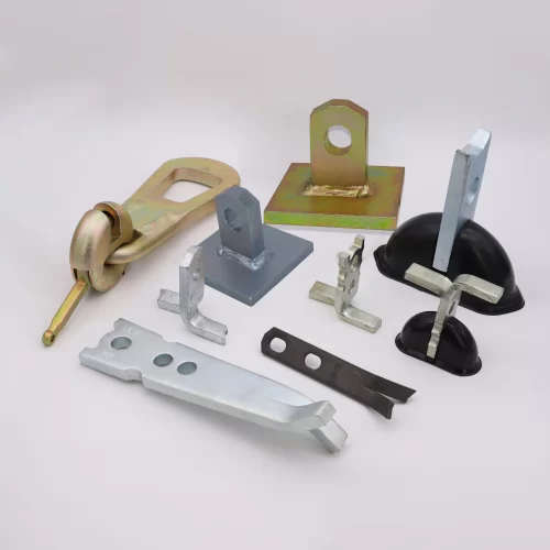
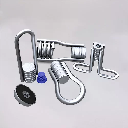
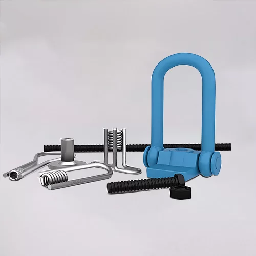
You can click to learn more about HULK Metal precast concrete accessories such as lifting anchors, precast sockets, spread anchors, shuttering magnets, cast-in channels, wire loop boxes, and other precast concrete accessories you might want to know.