



How to Choose the Correct Threaded Lifting Socket?
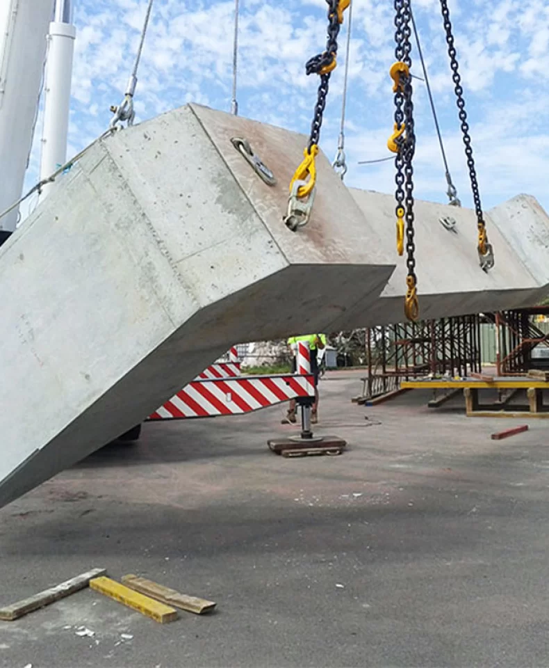
In precast concrete production, threaded lifting sockets are the critical link between a finished concrete element and the lifting device used during demoulding, rotation, transport, and installation. They transfer load from the lifting eye into the concrete body through a designed anchorage system, not through the thread alone.
Selecting a socket based only on thread size or a nominal load rating is one of the most common causes of lifting incidents. A socket that "looks right" can fail during tilt-up, rotation, or final installation if the anchorage, embedment, reinforcement layout, concrete strength, or mating lifting device has not been verified for that specific application.
The correct approach considers six interlinked factors: the application, the load requirements, thread compatibility, anchorage design, concrete conditions, and quality documentation. This article gives engineers, precast concrete manufacturers, procurement managers, and distributors a practical framework for choosing and verifying a threaded lifting socket.
Understand the Application and Lifting Requirements
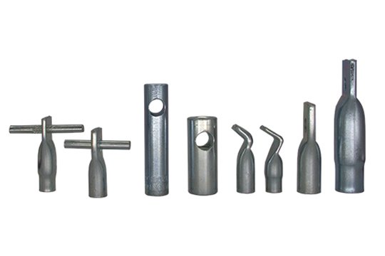
Identify the Intended Use
Threaded lifting sockets are engineered for lifting, handling, and installation of precast concrete elements. They are not interchangeable with ordinary fixing inserts, which are designed to receive only static loads from façade brackets, handrails, service pipes, or equipment supports. A product that is not explicitly documented and approved for lifting must never be used in a lifting system, even if the thread appears identical.
Typical applications include precast wall panels, beams, columns, slabs, stairs, and infrastructure elements such as tunnel segments or utility chambers. Each element type places different demands on embedment depth, socket position, and reinforcement layout.
Evaluate the Lifting Conditions
Before a socket model is selected, the responsible engineer should determine the element weight and centre of gravity, the number, position, and orientation of the planned lifting points, and the full sequence of operations — demoulding, rotation (90° or tilting), transport, storage, and final installation. The compressive strength of the concrete at the time of first lift and any dynamic effects such as slewing, hoisting acceleration, or uneven sling tension must also be considered. These conditions define the design loads and the permissible loading directions that the socket, its anchorage, and the compatible lifting device must be capable of carrying.
Select the Appropriate Socket Type and Anchorage Structure
Threaded Socket with Reinforcing Bar
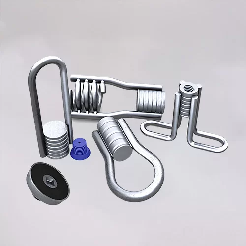
A bar-tail socket uses a reinforcing bar welded to the threaded body to transfer tension into the concrete through bond and the engineered reinforcement pattern. It is the most common design for standard precast elements and requires the bar length, diameter, and bend configuration to match the approved technical documentation. This arrangement is used wherever a defined reinforcement layout can be installed around the socket.
Threaded Socket with Cross-Hole or Other Restraint
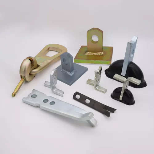
Cross-hole, headed, and plate-type anchorage arrangements are used where embedment depth is limited or where a defined mechanical interlock is preferred over bar bond. Each arrangement has specific installation requirements and load-transfer principles documented by the manufacturer. The chosen design must always match the element geometry, the available reinforcement cage, and the approved anchorage detail on the engineering drawings.
Consider Element Thickness and Edge Distance
Concrete thickness, edge distance, spacing between lifting points, and the position of surrounding reinforcement all constrain which socket can be installed. Limited installation space is often the deciding factor in thin panels, double-tees, or narrow beams. The selected anchorage configuration must be confirmed through the project's engineering drawings and the manufacturer's published technical data, not estimated in the field.
Verify Thread Specifications and Lifting Device Compatibility
Confirm the Exact Thread Type and Size
Thread specifications must always be written in full. "M20" is not sufficient; the thread profile, pitch, tolerance class (such as Metric ISO 6H or Rd thread per DIN 405), engagement length, and seating face must all be confirmed against the mating component. A socket's working performance depends on the complete thread designation, not just the nominal diameter.
Match the Socket with the Correct Lifting Device
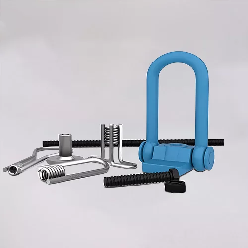
A socket works only as part of an approved lifting assembly. Compatible devices include lifting eyes, threaded lifting loops, swivel lifting devices, and other accessories produced or explicitly approved by the socket manufacturer. Physical thread fit does not, by itself, establish safe compatibility: the permitted loading direction, locking mechanism, seating surface, and pre-lift inspection requirements must also be verified. Components from different manufacturers should never be mixed without documented compatibility approval, as this creates an immediate lifting-safety exposure.
Evaluate Material, Surface Finish, and Corrosion Protection
Material selection depends on the service environment. Carbon steel is standard for most precast applications, while stainless steel is specified where the element is exposed to chlorides, marine atmospheres, or aggressive chemicals. Finishes may include plain steel, electro-galvanizing, or hot-dip galvanizing, where available and approved for the specific product. Hot-dip coatings in particular must remain compatible with thread tolerances and lifting-device engagement. The selected steel grade, coating, dimensional tolerance, and traceability records should all be verified before order release, and any material or finish substitution requires technical review rather than unilateral procurement decision.
Check Installation Requirements and Thread Protection
Correct installation is as critical as correct selection. Before casting, confirm socket position, orientation, and embedment depth; the fixing method (recess former, fixing plate, nailing plate, or magnetic holder); formwork compatibility and any required sealing; and the use of thread caps or plugs during casting, transport, and storage. After demoulding, remove all concrete slurry, dust, and any visible thread damage before the first lift, and inspect each socket for seating and thread condition. The manufacturer's current installation and maintenance instructions always take precedence over general site practice.
Verify Load Capacity, Testing, and Quality Documentation
A rated capacity is only valid when it applies to the complete approved lifting arrangement, in the documented loading direction, at the documented concrete strength. A catalogue value is not, by itself, a guarantee for the project at hand.
Documentation to request and review before purchase includes technical drawings and product specifications, test reports covering the exact product model, size, and revision, material certificates with batch traceability, and inspection records for dimensional accuracy, thread quality, and surface condition. Selecting products based solely on a supplier's general quality certificate or an unqualified load rating is a frequent root cause of field failures; certification must match the product being supplied.
Practical Purchasing Checklist
Selection Factor | Information to Verify |
| Application | Intended lifting operation and concrete element type |
| Load Requirements | Element weight, lifting points, load directions, and approved design basis |
| Socket Structure | Bar tail, cross-hole, head, plate, or other specified anchorage |
| Thread Specifications | Complete thread designation and compatible lifting device |
| Concrete Conditions | Thickness, edge distance, reinforcement layout, and embedment |
| Material and Finish | Specified steel grade and corrosion protection |
| Installation | Fixing method, recess, orientation, and thread protection |
| Quality Documentation | Drawings, test reports, inspection records, and traceability |
| Procurement | Quantity, packaging, delivery requirements, and approved product revision |
Common Mistakes to Avoid
Choosing a socket based only on thread diameter, confusing a fixing insert with a lifting-rated socket, ignoring reinforcement requirements, assuming cross-manufacturer component compatibility, overlooking concrete strength at the time of first lift, and accepting incomplete technical documentation are the recurring errors behind lifting incidents. Each one on its own can lead to installation problems, procurement delays, and serious safety risks. Verifying the complete assembly — socket, anchorage, concrete element, and lifting device — is the only reliable defence.
Why Choose HULK Metal for Threaded Lifting Sockets
HULK Metal supplies precast concrete accessories and metal OEM solutions, focusing on the practical requirements of engineers and buyers. The company supports project-specific thread specifications, dimensions, materials, and finishes, subject to engineering review. Dimensional inspection, material verification, and applicable testing records are part of the routine order process, and coordinated sourcing, production, inspection, packaging, and logistics support order execution from quotation through delivery.
Buyers are encouraged to share drawings, thread details, load requirements, and application information before ordering, so the proposed socket can be matched to the project.
Article Navigation
PRECAST CONCRETE ACCESSORIES
Other Precast Concrete Accessories You Might Want to Know
You can click to learn more about HULK Metal precast concrete accessories such as lifting anchors, precast sockets, spread anchors, shuttering magnets, cast-in channels, wire loop boxes, and other precast concrete accessories you might want to know.