



Lifting Loops: Guide for Safe Material Handling
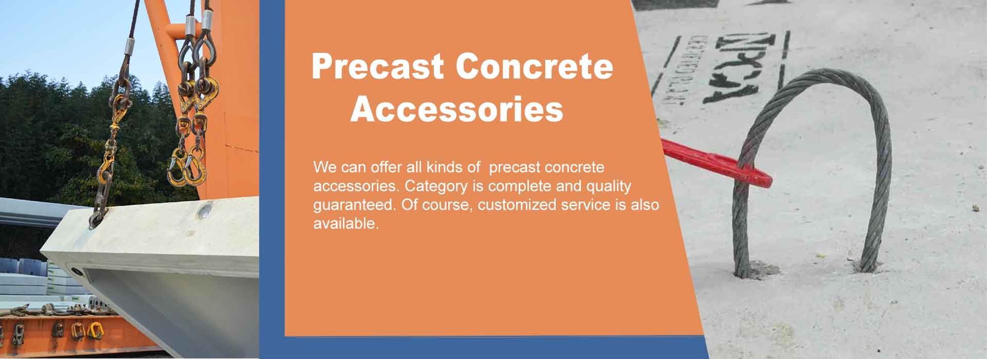
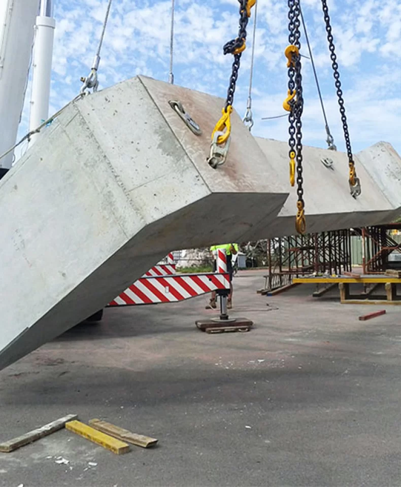
Lifting loops play an important role in safe material handling, particularly in precast concrete production, transportation, and on-site installation. Their performance depends not only on the strength of the lifting loop itself but also on the quality of its connection to the lifting socket, the condition of the surrounding concrete, and the lifting method used.
In practical applications, a lifting loop is commonly connected to a compatible lifting socket through a specified threaded connection. If the thread engagement is insufficient, the seating surfaces are not properly aligned, or the lifting direction exceeds the permitted range, the entire lifting operation may be exposed to unnecessary risks.
For precast concrete manufacturers, construction contractors, and procurement professionals, understanding these factors helps improve lifting safety, reduce equipment damage, and maintain consistent handling efficiency.
This guide examines the key factors affecting lifting loop performance, explains how to verify compatibility with lifting sockets, and outlines practical inspection and supplier selection procedures for demanding material handling applications.
1. How Lifting Loops Work with Lifting Sockets
A lifting loop and its compatible lifting socket must function as a coordinated connection during lifting. The threaded connection transfers the applied force through the contact surfaces and into the embedded socket and surrounding concrete.
The reliability of this connection depends on several factors:
- Thread compatibility: The thread diameter, pitch, profile, and tolerance must match the specified socket.
- Thread engagement: The lifting loop must achieve the engagement required by the product design.
- Seating condition: The designated contact surfaces must be properly seated without unintended gaps or obstructions.
- Load direction: The connection must remain within its approved loading conditions.
- Concrete condition: The surrounding concrete must have sufficient strength to resist the forces generated during lifting.
A lifting loop that appears to fit a socket is not necessarily suitable for use. Similar thread diameters do not guarantee identical thread profiles or pitches, and forcing an incompatible component into a socket can damage the threads.
For this reason, buyers and operators should verify the complete connection specification before the first lift. Components should only be combined when their compatibility has been established through approved technical documentation or confirmation from the manufacturer.
2. Critical Factors Affecting Lifting Loop Performance
2.1 Thread Compatibility and Engagement
Threaded connections are among the most important inspection points in a lifting loop assembly. The connection must distribute the applied load according to the intended design rather than concentrate excessive stress on a limited number of threads.
Before installation, verify the following:
- Thread designation and profile.
- Nominal diameter and pitch.
- Required engagement length.
- Thread condition and cleanliness.
- Compatibility between the lifting loop and lifting socket.
Metric and round-thread systems, for example, may appear similar but use different thread geometries. A connection should never be approved based on appearance or the ability to turn the loop into the socket.
Cross-threading can damage the mating surfaces and prevent the connection from achieving the required engagement. If abnormal resistance occurs during installation, stop and inspect the components instead of applying additional force.
The required engagement and seating criteria should follow the manufacturer's instructions. Where a specific installation torque is required, use the stated value and an appropriate method of verification rather than relying on subjective hand-tightness.
2.2 Seating Surface and Connection Alignment
Correct thread engagement alone does not guarantee a reliable connection. The seating surfaces must also meet the requirements of the product design.
Dirt, concrete residue, corrosion products, coating buildup, or other contamination may prevent proper seating. An unintended gap between contact surfaces can introduce eccentric loading and increase bending stress in components designed primarily for axial tension.
Before lifting, check that the lifting loop is correctly aligned and fully seated as specified. Do not compensate for poor seating by forcing the connection or using unauthorized modifications.
If the socket or surrounding concrete is damaged, displaced, or incorrectly installed, the assembly should be assessed before use.
2.3 Load Capacity and Force Distribution
The rated capacity of a lifting loop assembly must be considered in relation to the actual lifting conditions. The total weight of a precast concrete element is only the starting point for evaluating the required capacity.
Other relevant factors include:
- The number and location of lifting points.
- The position of the centre of gravity.
- The angle between sling legs and the vertical.
- Unequal load distribution among lifting points.
- Dynamic effects during lifting and lowering.
- Additional resistance during demoulding.
For example, when sling legs are inclined, the tension in each leg generally increases compared with a vertical arrangement supporting the same load share. Unequal sling lengths or incorrectly positioned lifting points can further increase the force carried by individual connections.
Do not assume that each lifting loop carries an equal share of the load simply because several lifting points are used. The lifting arrangement must be evaluated according to the approved engineering design.
The capacity of the lifting loop, lifting socket, connecting equipment, and supporting concrete must all be sufficient for their respective loading conditions.
3. The Role of Concrete Quality in Lifting Safety
Although the lifting loop connects directly to the lifting socket, the performance of the complete assembly also depends on the concrete surrounding the embedded socket.
3.1 Verify Concrete Strength Before Lifting
Precast concrete components are often lifted during demoulding, when the concrete has not yet reached its final design strength. The strength required for safe lifting may differ from the strength specified for the completed structure.
Before lifting, confirm that the concrete has reached the minimum strength required by the approved lifting design. Do not rely solely on elapsed curing time or assume that reaching 28-day strength is the only relevant criterion.
Demoulding suction, handling acceleration, and the geometry of the component may introduce additional forces that must be considered during planning.
3.2 Check Socket Position and Embedment
The location and installation quality of the lifting socket influence how the lifting force is transferred into the concrete.
Before the first lift, compare the actual socket positions with the approved drawing. Check for incorrect orientation, insufficient edge distance, inadequate embedment, and visible defects around the embedded area.
Incorrect placement can change the intended load distribution and increase the risk of local concrete damage. Insufficient consolidation may also leave voids around the embedded component, reducing the reliability of the connection.
Any deviation that could affect lifting capacity should be reviewed by a competent engineer before the component is lifted.
4. Essential Safety Checks Before Using Lifting Loops
A structured inspection helps identify defects before the lifting operation begins. The inspection should cover the complete assembly rather than focusing only on the visible lifting loop.
4.1 Inspect the Lifting Loop
Check the lifting loop for:
- Cracks, deformation, or unusual changes in shape.
- Excessive wear, corrosion, or loss of material.
- Damaged threads or signs of cross-threading.
- Defects at the connection shoulder or other highly stressed areas.
- Missing or illegible product identification.
For wire rope lifting loops, inspect for broken wires, kinks, crushing, or other defects relevant to the product design. Apply the manufacturer's rejection criteria and applicable safety requirements.
4.2 Inspect the Lifting Socket and Connection
Before assembling the lifting loop, confirm that the lifting socket is clean, correctly positioned, and free from visible damage that could affect its performance.
For threaded connections, check the thread condition and remove contamination using an approved cleaning method. Verify that the lifting loop engages correctly and reaches the specified seating position.
Do not use damaged sockets, force incompatible threads together, or rely on an apparently tight connection as proof of correct engagement.
4.3 Inspect the Complete Lifting Arrangement
The inspection should also cover hooks, slings, shackles, and other connecting equipment used in the lifting operation.
Confirm that each component is suitable for the intended load and compatible with the rest of the assembly. Check the lifting plan, verify the load distribution, and ensure that the lifting direction remains within the permitted range.
Personnel must remain clear of suspended loads, and no one should stand or work beneath a suspended precast concrete element.
5. Common Problems with Lifting Loop Assemblies
These problems can often be prevented through clear installation procedures, appropriate operator training, and consistent quality control.
6. Maintenance and Inspection of Reusable Lifting Loops
Where lifting loops are designed for repeated use, inspection and maintenance should follow the manufacturer's documented requirements.
Each component should be checked before use and after any event that may have caused damage, such as overloading, impact, or abnormal loading. Additional inspection intervals should be established according to the equipment type, frequency of use, operating environment, and applicable regulations.
Components showing cracks, permanent deformation, damaged threads, or other defects that exceed the permitted limits must be removed from service. Unauthorized welding, reshaping, or repair should not be used to restore a component to service.
Traceability is also important. Records should identify the equipment, relevant inspection results, and any defects or actions taken. Where required, batch identification and test documentation should be retained to support quality management.
A consistent inspection procedure reduces reliance on individual judgment and helps prevent damaged equipment from returning to service unnoticed.
7. How to Choose a Reliable Lifting Loop Supplier
Selecting a capable supplier is essential for maintaining product consistency and ensuring that lifting loops meet the requirements of the intended application.
7.1 Verify Manufacturing and Quality Control
Review the supplier's manufacturing capabilities and quality-control procedures. Relevant controls may include raw-material verification, dimensional inspection, thread gauging, production process monitoring, and appropriate mechanical testing.
For lifting loops and related components, the inspection methods should be suitable for the product design and its intended loading conditions.
7.2 Request Product-Specific Technical Documents
Before placing an order, request the documentation needed to verify product suitability, such as:
- Technical drawings and dimensional specifications.
- Thread designation and compatibility requirements.
- Rated load information and permitted loading directions.
- Installation and inspection instructions.
- Applicable test reports and traceability records.
- Relevant certification or conformity documentation.
A general company quality certificate should not be treated as a substitute for product-specific evidence.
7.3 Evaluate Customization and Delivery Capabilities
For OEM projects, confirm whether the supplier can manufacture according to approved drawings, specified materials, surface treatments, order quantities, and quality requirements.
Production planning, packaging, delivery coordination, and after-sales support also affect procurement efficiency. A supplier with clear technical communication and documented quality processes can help reduce misunderstandings and avoidable delays.
HULK Metal provides metal manufacturing and OEM services, including support for customers sourcing customized metal components and precast concrete accessories. By reviewing drawings, technical requirements, and order quantities, HULK Metal can help coordinate production and quality-control arrangements for specific projects.
Buyers can submit their drawings and specifications to discuss manufacturing feasibility, quality requirements, and quotation details.
Safe material handling depends on the correct selection, installation, and inspection of the complete lifting assembly. For lifting loops used with lifting sockets, thread compatibility, proper engagement, correct seating, and suitable loading conditions are essential to reliable performance.
Concrete strength, socket placement, rigging geometry, and equipment condition must also be verified before lifting. By establishing clear procedures and maintaining appropriate inspection records, precast concrete manufacturers and construction teams can reduce preventable risks and improve operational efficiency.
Choosing a supplier with reliable manufacturing capabilities, product-specific documentation, and responsive technical support further strengthens quality control. For customized lifting loop requirements, buyers can contact HULK Metal with their drawings, specifications, and order quantities to discuss a suitable manufacturing solution.
Article Navigation
PRECAST CONCRETE ACCESSORIES
Other Precast Concrete Accessories You Might Want to Know
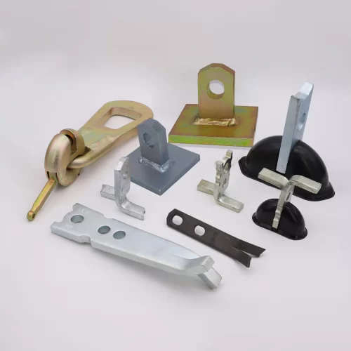
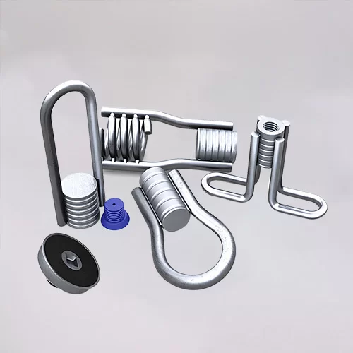
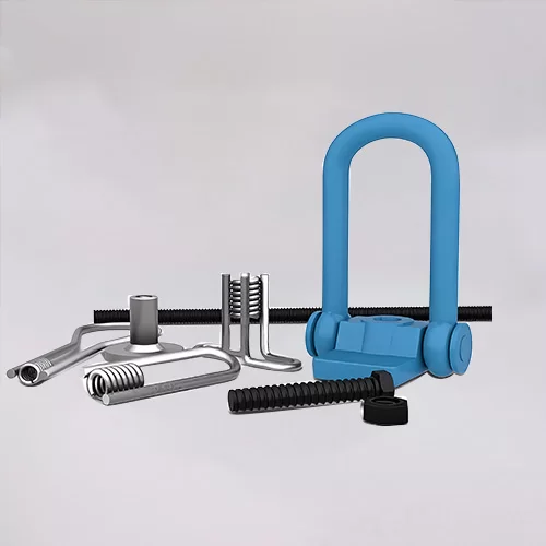
You can click to learn more about HULK Metal precast concrete accessories such as lifting anchors, precast sockets, spread anchors, shuttering magnets, cast-in channels, wire loop boxes, and other precast concrete accessories you might want to know.