



Why Pull Testing Determines Lifting Safety?
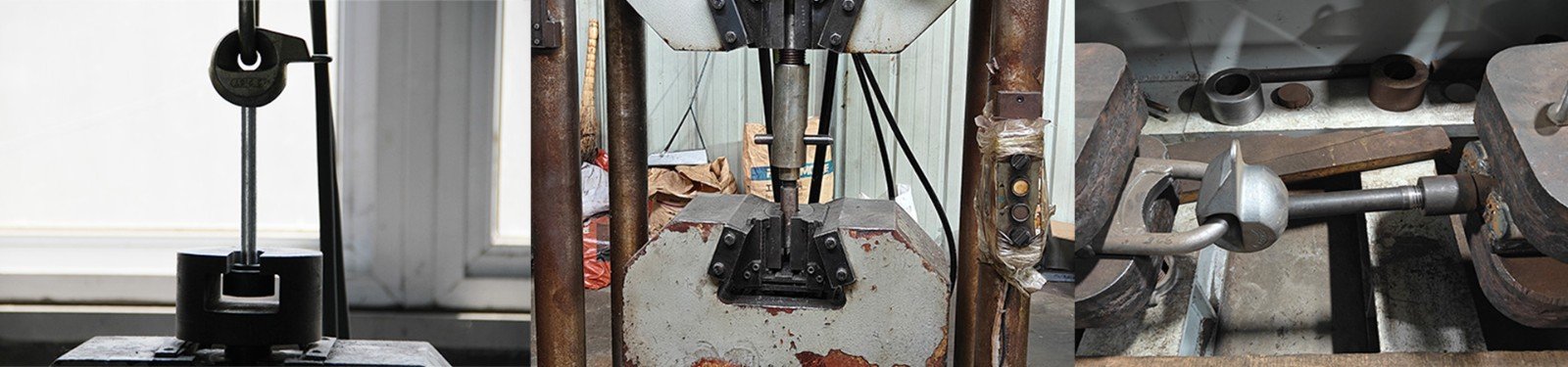
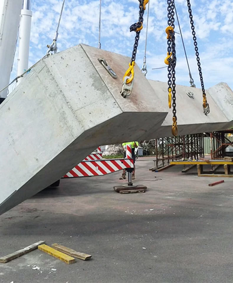
Every stage of precast concrete production—manufacturing, transport, and installation—depends on one physical event: a concrete element weighing several tonnes is lifted from one position and held suspended in another. At that moment, the entire load path runs through a small number of components: the anchor embedded in the concrete, the clutch or socket that engages it, and the connection hardware above. If any one link underperforms, the consequences are immediate and severe—component fracture, concrete breakout, dropped loads, and serious injury to anyone working below.
Pull testing exists to prevent that outcome. By applying a controlled tensile load to a lifting component or an installed anchor system, manufacturers obtain documented evidence that the product performs as designed before it reaches a construction site. Using lifting products without adequate testing is not a calculated risk; it is an unmeasured one. Under-strength steel, inconsistent material, or an inadequately reinforced anchorage zone reveal themselves at the worst possible moment.
The argument of this article is straightforward: reliable lifting safety depends on verified mechanical performance, correct installation, and consistent compliance with applicable design requirements—and pull testing is the primary means by which that performance is verified.
What Is Pull Testing for Lifting Components?
Definition and Basic Principles
Pull testing applies a controlled, gradually increased tensile load to a component and records its response: load carried, deformation, displacement, and where relevant the mode of failure. Two evaluations sit under this umbrella. The first tests the metal component itself—an anchor, socket or clutch loaded in a calibrated machine. The second, more important for precast work, tests the installed system: an anchor embedded in concrete, loaded to evaluate the combined performance of steel and surrounding anchorage.
Both produce meaningful results only when three elements are fixed in advance: the test load, the loading procedure, and the acceptance criteria. A test without a defined pass/fail threshold is not quality control—it is an observation.
Common Pull Testing Methods
Proof Load Testing applies a specified load, typically a defined multiple of the working load, to confirm the component withstands it without permanent deformation or other unacceptable behavior. It is the workhorse of production quality control.
Ultimate Tensile Testing increases load until the specimen fails or reaches its defined ultimate capacity, establishing the actual failure margin of a design or batch.
On-Site Pull-Out Testing evaluates an installed anchor within a real concrete element, verifying that the as-built assembly—including concrete strength and reinforcement—performs as the design assumes.
Pull Testing vs. Other Quality Tests
Pull testing does not stand alone. Magnetic particle inspection detects surface and near-surface cracks. Dimensional inspection confirms geometric conformity. Hardness testing and material verification confirm that the steel matches specification. Each answers a different question, and none substitutes for another: a dimensionally perfect anchor made from the wrong steel passes a dimensional check and fails a tensile test, while a sound steel component in poorly reinforced concrete passes a component test and fails a pull-out test. Effective quality programs use these methods in combination.
Why Pull Testing Determines Lifting Safety
Verifying Load-Bearing Capacity
The core purpose is to confirm that anchors, sockets and other load-bearing components actually meet specified mechanical requirements. This requires separating three values that are frequently confused: the rated working load (the load a component is certified to lift in service), the proof load (the elevated load applied during verification), and the ultimate failure load (the load at which the specimen fails). These are related by defined safety factors, and results must be interpreted against the product specification—never against intuition or comparison with a competitor's catalogue.
Identifying Potential Manufacturing Defects
A mature, validated design can still be compromised by production variables: a heat treatment batch outside tolerance, an inconsistent weld, a material substitution, or a forming defect hidden inside the steel. Testing representative samples exposes these weaknesses as measurable shortfalls in load performance. For that exposure to be useful, however, testing must be paired with material traceability and in-process inspection, so an underperforming sample leads to a specific batch being identified, isolated and investigated rather than quietly absorbed into shipments.
Reducing the Risk of Component Failure
Verified performance directly reduces the probability of the failure modes that dominate lifting accidents: plastic deformation, brittle fracture, thread stripping, and concrete cone breakout. The value lies in the sampling logic—testing representative samples from each production batch under controlled conditions provides statistical confidence that untested components from the same batch behave identically.
Supporting Consistent Product Quality
Beyond pass/fail verdicts, test data accumulates into a production history. Tracking ultimate loads and deformation behavior over time reveals gradual drift—a slowly declining failure load may point to tooling wear or a raw material change—long before it causes a failure. Traceable records also serve buyers, giving them objective evidence for supplier evaluation and incoming quality verification.
Which Lifting Components Require Pull Testing?
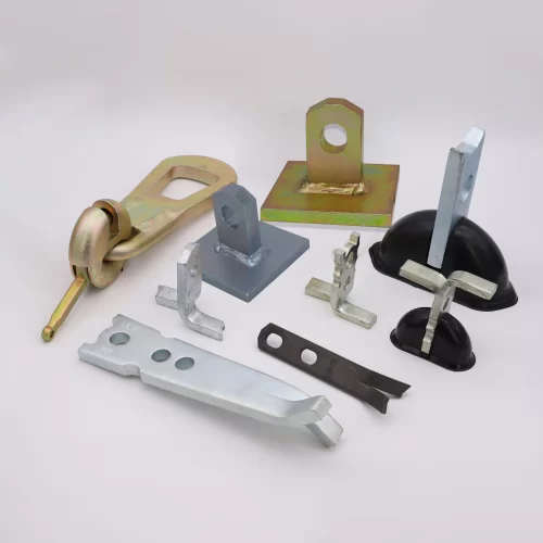
Lifting anchors require tensile verification against their specified load requirements, with the test configuration reflecting anchor geometry, material grade, manufacturing method and intended lifting direction. An anchor validated for axial loading cannot be assumed adequate at an angle.
Threaded lifting sockets and inserts must be evaluated as an anchorage configuration, not merely as a threaded part: verification covers the insert body, its head or tail geometry, and its engagement with the concrete, together with thread compatibility, embedment depth and the connection system it was designed for.
Lifting clutches and connecting components transmit load from crane to anchor, and their performance should be verified as a complete connection where required. Critically, clutch and anchor must be checked as a designated compatible system—mixing systems without validation is a well-documented cause of disengagement failures.
Embedded anchors in precast concrete add further variables: concrete strength at the time of lifting, edge distance, embedment depth, reinforcement arrangement and loading direction all influence results. Component testing alone cannot predict the behavior of the anchor–concrete assembly; both levels are necessary.
How a Reliable Pull Testing Process Works
Step 1 — Define the test requirements. Identify the component, its rated working load, the test objective, the applicable specification, and—before anything is loaded—the acceptance criteria.
Step 2 — Prepare the specimen and equipment. Verify specimen identification and batch traceability, confirm fixture compatibility, and confirm that the test machine and load measurement system are within calibration.
Step 3 — Apply the specified load. Load according to the prescribed procedure, holding or ramping as specified, while monitoring deformation, displacement or other required parameters throughout.
Step 4 — Record and evaluate the results. Document applied load, observed behavior, test conditions and failure mode, then compare against the predefined acceptance criteria rather than an after-the-fact judgment.
Step 5 — Maintain traceable quality records. Link every report to product specifications, production batches, material certificates and inspection results, forming an unbroken chain from raw steel to shipped product.
Factors That Affect Pull Testing Results
Material properties: steel grade, heat treatment condition, and material consistency within and between heats.
Component design: geometry, load-bearing cross-sections, weld placement and quality, anchorage structure.
Concrete conditions: strength at time of test, curing, existing cracking, embedment depth.
Test setup: loading direction relative to the anchor axis, fixture alignment, equipment calibration.
Installation quality: positioning accuracy, reinforcement around the anchorage zone, installation tolerances.
Testing procedures: load application rate, test method, sampling frequency, acceptance criteria.
Misalignment alone can degrade a measured capacity enough to turn a compliant product into an apparent failure. A result is only as meaningful as the control exercised over these variables.
Common Mistakes in Pull Testing and Lifting Safety
Treating the ultimate failure load as the allowable working load, discarding the safety factor entirely.
Applying test loads without a defined engineering basis—chosen by custom or imitation rather than specification.
Testing the metal component thoroughly while never evaluating the concrete anchorage in which it works.
Ignoring the effects of eccentric, inclined or dynamic loading, which can multiply effective loads well beyond the static case.
Combining clutches and anchors that were never approved as a compatible system.
Failing to maintain inspection records, or failing to investigate samples that underperformed—either omission reduces quality control to a formality.
Assuming a successful test removes the need for correct installation and disciplined lifting procedures. A certified anchor poorly installed is an uncertified anchor.
How Buyers Can Evaluate a Lifting Component Supplier
Buyers can apply these principles through four checks. Ask for relevant test reports, and confirm they identify the product, the test method, the applied load, the results and the acceptance criteria used. Verify material traceability by requesting material certificates and batch identification linking delivered product to its raw material source. Review quality management and inspection procedures—incoming material inspection, in-process checks, final inspection, and the frequency and arrangement of tensile testing. Confirm standards applicability and product compatibility: verify which standards and technical requirements apply to the specific product and system, and ensure declared load capacity and intended application are documented clearly. A supplier who cannot answer these questions fluently is telling the buyer something important.
How HULK Metal Supports Lifting Product Quality
At HULK Metal, lifting component quality is built on controlled manufacturing processes and systematic inspection rather than end-of-line sorting. Dimensional verification, material checks, magnetic particle inspection where applicable, and tensile testing are integrated into the production sequence, each stage documented and traceable from raw material to finished product.
That documentation discipline matters as much as the testing itself: every shipment can be supported by records verifying what was made, from what material, and to what verified performance. For buyers with specific requirements, HULK Metal encourages submission of drawings, load requirements, material specifications and application details for technical review before production, so that the testing regime matches the service conditions the components will actually face.
Pull testing provides essential, verifiable evidence of mechanical performance—but only under appropriate conditions, with defined loads, controlled setups and predetermined acceptance criteria. It is the foundation of lifting safety, not the whole structure. Safe lifting ultimately depends on sound engineering design, adequate concrete conditions, compatible equipment used as an approved system, correct installation, and trained personnel following disciplined procedures.
The practical takeaway for buyers is to select lifting components supported by relevant test evidence and a reliable quality management process. For lifting component manufacturing with full quality documentation and technical review, contact HULK Metal to discuss your project requirements.
Article Navigation
PRECAST CONCRETE ACCESSORIES
OTHER RELATED ARTICLE
- 1.How Efficient Precast Accessories Improve Construction Productivity?
- 2.How to Choose High-Quality Shuttering Magnetic Products and Suppliers Guide
- 3.Applications and advantages of swivel hoist rings: HULK Metal provides you with safer and more flexible lifting solutions
- 4.Lifting Clutch VS Lifting Ring Clutch:Definition, Working Principle, Application Scenarios, and Selection Guide
- 5.An In-Depth Guide to Erection Anchors, Single-Hole Spread Anchors and Two-Hole Spread Anchors
Other Precast Concrete Accessories You Might Want to Know
You can click to learn more about HULK Metal precast concrete accessories such as lifting anchors, precast sockets, spread anchors, shuttering magnets, cast-in channels, wire loop boxes, and other precast concrete accessories you might want to know.